Series and parallel circuits

A series circuit with a voltage source (such as a battery, or in this case a cell) and 3 resistors
Components of an electrical circuit or electronic circuit can be connected in many different ways. The two simplest of these are called series and parallel and occur frequently. Components connected in series are connected along a single path, so the same current flows through all of the components.[1][2] Components connected in parallel are connected along multiple paths, so the same voltage is applied to each component.[3]
A circuit composed solely of components connected in series is known as a series circuit; likewise, one connected completely in parallel is known as a parallel circuit.
In a series circuit, the current through each of the components is the same, and the voltage across the circuit is the sum of the voltages across each component.[1] In a parallel circuit, the voltage across each of the components is the same, and the total current is the sum of the currents through each component.[1]
Consider a very simple circuit consisting of four light bulbs and one 6 V battery. If a wire joins the battery to one bulb, to the next bulb, to the next bulb, to the next bulb, then back to the battery, in one continuous loop, the bulbs are said to be in series. If each bulb is wired to the battery in a separate loop, the bulbs are said to be in parallel. If the four light bulbs are connected in series, there is the same current through all of them, and the voltage drop is 1.5 V across each bulb, which may not be sufficient to make them glow. If the light bulbs are connected in parallel, the currents through the light bulbs combine to form the current in the battery, while the voltage drop is across each bulb and they all glow.
In a series circuit, every device must function for the circuit to be complete. One bulb burning out in a series circuit breaks the circuit. In parallel circuits, each light bulb has its own circuit, so all but one light could be burned out, and the last one will still function.
Contents
1 Series circuits
1.1 Current
1.2 Resistors
1.3 Inductors
1.4 Capacitors
1.5 Switches
1.6 Cells and batteries
1.7 Voltage
2 Parallel circuits
2.1 Voltage
2.2 Current
2.3 Resistors
2.4 Inductors
2.5 Capacitors
2.6 Switches
2.7 Cells and batteries
3 Combining conductances
4 Notation
5 Applications
6 See also
7 Notes
8 References
9 External links
Series circuits
| Part of a series of articles about |
| Electromagnetism |
|---|
 |
|
Electrostatics
|
Magnetostatics
|
Electrodynamics
|
Electrical network
|
Covariant formulation
|
Scientists
|
Series circuits are sometimes called current-coupled or daisy chain-coupled. The current in a series circuit goes through every component in the circuit. Therefore, all of the components in a series connection carry the same current.
A series circuit's principal characteristic is that it has only one path in which its current can flow. Opening or breaking a series circuit at any point causes the entire circuit to "open" or stop operating. For example, if even one of the light bulbs in an older-style string of Christmas tree lights burns out or is removed, the entire string becomes inoperable until the bulb is replaced.
Current
- I=I1=I2=I3=⋯=In{displaystyle I=I_{1}=I_{2}=I_{3}=cdots =I_{n}}

In a series circuit, the current is the same for all of the elements.
Resistors
The total resistance of resistors in series is equal to the sum of their individual resistances:
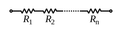
- Rtotal=Rs=R1+R2+⋯+Rn{displaystyle R_{text{total}}=R_{text{s}}=R_{1}+R_{2}+cdots +R_{n}}

Rs=>Resistance in series
Electrical conductance presents a reciprocal quantity to resistance. Total conductance of a series circuits of pure resistors, therefore, can be calculated from the following expression:
1Gtotal=1G1+1G2+⋯+1Gn{displaystyle {frac {1}{G_{mathrm {total} }}}={frac {1}{G_{1}}}+{frac {1}{G_{2}}}+cdots +{frac {1}{G_{n}}}}.
For a special case of two resistors in series, the total conductance is equal to:
- Gtotal=G1G2G1+G2.{displaystyle G_{text{total}}={frac {G_{1}G_{2}}{G_{1}+G_{2}}}.}

Inductors
Inductors follow the same law, in that the total inductance of non-coupled inductors in series is equal to the sum of their individual inductances:

- Ltotal=L1+L2+⋯+Ln{displaystyle L_{mathrm {total} }=L_{1}+L_{2}+cdots +L_{n}}

However, in some situations, it is difficult to prevent adjacent inductors from influencing each other, as the magnetic field of one device coupled with the windings of its neighbours. This influence is defined by the mutual inductance M. For example if two inductors are in series, there are two possible equivalent inductances depending on how the magnetic fields of both inductors influence each other.
When there are more than two inductors, the mutual inductance between each of them and the way the coils influence each other complicates the calculation. For a larger number of coils the total combined inductance is given by the sum of all mutual inductances between the various coils including the mutual inductance of each given coil with itself, which we term self-inductance or simply inductance. For three coils, there are six mutual inductances M12{displaystyle M_{12}}


Therefore
- Ltotal=(M11+M22+M33)+(M12+M13+M23)+(M21+M31+M32){displaystyle L_{mathrm {total} }=(M_{11}+M_{22}+M_{33})+(M_{12}+M_{13}+M_{23})+(M_{21}+M_{31}+M_{32})}

By reciprocity Mij{displaystyle M_{ij}}

Capacitors
Capacitors follow the same law using the reciprocals. The total capacitance of capacitors in series is equal to the reciprocal of the sum of the reciprocals of their individual capacitances:

1Ctotal=1C1+1C2+⋯+1Cn{displaystyle {frac {1}{C_{mathrm {total} }}}={frac {1}{C_{1}}}+{frac {1}{C_{2}}}+cdots +{frac {1}{C_{n}}}}.
Switches
Two or more switches in series form a logical AND; the circuit only carries current if all switches are closed. See AND gate.
Cells and batteries
A battery is a collection of electrochemical cells. If the cells are connected in series, the voltage of the battery will be the sum of the cell voltages. For example, a 12 volt car battery contains six 2-volt cells connected in series. Some vehicles, such as trucks, have two 12 volt batteries in series to feed the 24-volt system.
Voltage
In a series circuit the voltage is the sum of all voltages in the components.
- V=V1+V2+V3+⋯+Vn{displaystyle V=V_{1}+V_{2}+V_{3}+dots +V_{n}}

Parallel circuits
If two or more components are connected in parallel they have the same potential difference (voltage) across their ends. The potential differences across the components are the same in magnitude, and they also have identical polarities. The same voltage is applied to all circuit components connected in parallel. The total current is the sum of the currents through the individual components, in accordance with Kirchhoff’s current law.
Voltage
In a parallel circuit the voltage is the same for all elements.
- V=V1=V2=…=Vn{displaystyle V=V_{1}=V_{2}=ldots =V_{n}}

Current
The current in each individual resistor is found by Ohm's law. Factoring out the voltage gives
Itotal=V(1R1+1R2+⋯+1Rn){displaystyle I_{mathrm {total} }=Vleft({frac {1}{R_{1}}}+{frac {1}{R_{2}}}+cdots +{frac {1}{R_{n}}}right)}.
Resistors
To find the total resistance of all components, add the reciprocals of the resistances Ri{displaystyle R_{i}}

1Rtotal=1R1+1R2+⋯+1Rn{displaystyle {frac {1}{R_{mathrm {total} }}}={frac {1}{R_{1}}}+{frac {1}{R_{2}}}+cdots +{frac {1}{R_{n}}}}.
For only two resistors, the unreciprocated expression is reasonably simple:
- Rtotal=R1R2R1+R2.{displaystyle R_{mathrm {total} }={frac {R_{1}R_{2}}{R_{1}+R_{2}}}.}

This sometimes goes by the mnemonic product over sum.
For N equal resistors in parallel, the reciprocal sum expression simplifies to:
1Rtotal=N1R{displaystyle {frac {1}{R_{mathrm {total} }}}=N{frac {1}{R}}}.
and therefore to:
Rtotal=RN{displaystyle R_{mathrm {total} }={frac {R}{N}}}.
To find the current in a component with resistance Ri{displaystyle R_{i}}
Ii=VRi{displaystyle I_{i}={frac {V}{R_{i}}},}.
The components divide the current according to their reciprocal resistances, so, in the case of two resistors,
I1I2=R2R1{displaystyle {frac {I_{1}}{I_{2}}}={frac {R_{2}}{R_{1}}}}.
An old term for devices connected in parallel is multiple, such as multiple connections for arc lamps.
Since electrical conductance G{displaystyle G}
Gtotal=G1+G2+⋯+Gn{displaystyle G_{mathrm {total} }=G_{1}+G_{2}+cdots +G_{n}}.
The relations for total conductance and resistance stand in a complementary relationship: the expression for a series connection of resistances is the same as for parallel connection of conductances, and vice versa.
Inductors
Inductors follow the same law, in that the total inductance of non-coupled inductors in parallel is equal to the reciprocal of the sum of the reciprocals of their individual inductances:

1Ltotal=1L1+1L2+⋯+1Ln{displaystyle {frac {1}{L_{mathrm {total} }}}={frac {1}{L_{1}}}+{frac {1}{L_{2}}}+cdots +{frac {1}{L_{n}}}}.
If the inductors are situated in each other's magnetic fields, this approach is invalid due to mutual inductance. If the mutual inductance between two coils in parallel is M, the equivalent inductor is:
- 1Ltotal=L1+L2−2ML1L2−M2{displaystyle {frac {1}{L_{mathrm {total} }}}={frac {L_{1}+L_{2}-2M}{L_{1}L_{2}-M^{2}}}}

If L1=L2{displaystyle L_{1}=L_{2}}

- Ltotal=L+M2{displaystyle L_{text{total}}={frac {L+M}{2}}}

The sign of M{displaystyle M}
More than three inductors become more complex and the mutual inductance of each inductor on each other inductor and their influence on each other must be considered. For three coils, there are three mutual inductances M12{displaystyle M_{12}}
The pertinent equations are of the form:
vi=∑jLi,jdijdt{displaystyle v_{i}=sum _{j}L_{i,j}{frac {di_{j}}{dt}}}

Capacitors
The total capacitance of capacitors in parallel is equal to the sum of their individual capacitances:
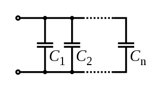
Ctotal=C1+C2+⋯+Cn{displaystyle C_{mathrm {total} }=C_{1}+C_{2}+cdots +C_{n}}.
The working voltage of a parallel combination of capacitors is always limited by the smallest working voltage of an individual capacitor.
Switches
Two or more switches in parallel form a logical OR; the circuit carries current if at least one switch is closed. See OR gate.
Cells and batteries
If the cells of a battery are connected in parallel, the battery voltage will be the same as the cell voltage, but the current supplied by each cell will be a fraction of the total current. For example, if a battery comprises four identical cells connected in parallel and delivers a current of 1 ampere, the current supplied by each cell will be 0.25 ampere. Parallel-connected batteries were widely used to power the valve filaments in portable radios, but they are now rare. Some solar electric systems have batteries in parallel to increase the storage capacity; a close approximation of total amp-hours is the sum of all amp-hours of in-parallel batteries.
Combining conductances
From Kirchhoff's circuit laws we can deduce the rules for combining conductances. For two conductances G1{displaystyle G_{1}}

- Ieq=I1+I2. {displaystyle I_{text{eq}}=I_{1}+I_{2}. ,}

Substituting Ohm's law for conductances gives
- GeqV=G1V+G2V {displaystyle G_{text{eq}}V=G_{1}V+G_{2}V ,}

and the equivalent conductance will be,
- Geq=G1+G2. {displaystyle G_{text{eq}}=G_{1}+G_{2}. ,}

For two conductances G1{displaystyle G_{1}}
- Veq=V1+V2. {displaystyle V_{text{eq}}=V_{1}+V_{2}. ,}

Substituting Ohm's law for conductance then gives,
- IGeq=IG1+IG2{displaystyle {frac {I}{G_{text{eq}}}}={frac {I}{G_{1}}}+{frac {I}{G_{2}}}}

which in turn gives the formula for the equivalent conductance,
- 1Geq=1G1+1G2.{displaystyle {frac {1}{G_{text{eq}}}}={frac {1}{G_{1}}}+{frac {1}{G_{2}}}.}

This equation can be rearranged slightly, though this is a special case that will only rearrange like this for two components.
- Geq=G1G2G1+G2.{displaystyle G_{text{eq}}={frac {G_{1}G_{2}}{G_{1}+G_{2}}}.}

Notation
The value of two components in parallel is often represented in equations by two vertical lines, ∥, borrowing the parallel lines notation from geometry.
- Req≡R1‖R2≡(R1−1+R2−1)−1≡R1R2R1+R2{displaystyle R_{mathrm {eq} }equiv R_{1}|R_{2}equiv left(R_{1}^{-1}+R_{2}^{-1}right)^{-1}equiv {frac {R_{1}R_{2}}{R_{1}+R_{2}}}}

This simplifies expressions that would otherwise become complicated by expansion of the terms. For instance:
R1‖R2‖R3≡R1R2R3R1R2+R1R3+R2R3{displaystyle R_{1}|R_{2}|R_{3}equiv {frac {R_{1}R_{2}R_{3}}{R_{1}R_{2}+R_{1}R_{3}+R_{2}R_{3}}}}.
Applications
A common application of series circuit in consumer electronics is in batteries, where several cells connected in series are used to obtain a convenient operating voltage. Two disposable zinc cells in series might power a flashlight or remote control at 3 volts; the battery pack for a hand-held power tool might contain a dozen lithium-ion cells wired in series to provide 48 volts.
Series circuits were formerly used for lighting in electric multiple units trains. For example, if the supply voltage was 600 volts there might be eight 70-volt bulbs in series (total 560 volts) plus a resistor to drop the remaining 40 volts. Series circuits for train lighting were superseded, first by motor-generators, then by solid state devices.
Series resistance can also be applied to the arrangement of blood vessels within a given organ. Each organ is supplied by a large artery, smaller arteries, arterioles, capillaries, and veins arranged in series. The total resistance is the sum of the individual resistances, as expressed by the following equation: Rtotal = Rartery + Rarterioles + Rcapillaries. The largest proportion of resistance in this series is contributed by the arterioles.[4]
Parallel resistance is illustrated by the circulatory system. Each organ is supplied by an artery that branches off the aorta. The total resistance of this parallel arrangement is expressed by the following equation: 1/Rtotal = 1/Ra + 1/Rb + ... 1/Rn. Ra, Rb, and Rn are the resistances of the renal, hepatic, and other arteries respectively. The total resistance is less than the resistance of any of the individual arteries.[4]
See also
- Network analysis (electrical circuits)
- Wheatstone bridge
- Y-Δ transform
- Voltage divider
- Current divider
- Combining impedances
- Equivalent impedance transforms
- Resistance distance
- Series-parallel partial order
Notes
^ abc Resnick et al. (1966), Chapter 32, Example 1.
^ Smith, R.J. (1966), page 21
^ Resnick et al.
^ ab Board Review Series: Physiology by Linda S. Costanzo pg. 74
References
- Resnick, Robert and Halliday, David (1966), Physics, Vol I and II, Combined edition, Wiley International Edition, Library of Congress Catalog Card No. 66-11527
- Smith, R.J. (1966), Circuits, Devices and Systems, Wiley International Edition, New York. Library of Congress Catalog Card No. 66-17612
- Williams, Tim, The Circuit Designer's Companion, Butterworth-Heinemann, 2005 .mw-parser-output cite.citation{font-style:inherit}.mw-parser-output .citation q{quotes:"""""""'""'"}.mw-parser-output .citation .cs1-lock-free a{background:url("//upload.wikimedia.org/wikipedia/commons/thumb/6/65/Lock-green.svg/9px-Lock-green.svg.png")no-repeat;background-position:right .1em center}.mw-parser-output .citation .cs1-lock-limited a,.mw-parser-output .citation .cs1-lock-registration a{background:url("//upload.wikimedia.org/wikipedia/commons/thumb/d/d6/Lock-gray-alt-2.svg/9px-Lock-gray-alt-2.svg.png")no-repeat;background-position:right .1em center}.mw-parser-output .citation .cs1-lock-subscription a{background:url("//upload.wikimedia.org/wikipedia/commons/thumb/a/aa/Lock-red-alt-2.svg/9px-Lock-red-alt-2.svg.png")no-repeat;background-position:right .1em center}.mw-parser-output .cs1-subscription,.mw-parser-output .cs1-registration{color:#555}.mw-parser-output .cs1-subscription span,.mw-parser-output .cs1-registration span{border-bottom:1px dotted;cursor:help}.mw-parser-output .cs1-ws-icon a{background:url("//upload.wikimedia.org/wikipedia/commons/thumb/4/4c/Wikisource-logo.svg/12px-Wikisource-logo.svg.png")no-repeat;background-position:right .1em center}.mw-parser-output code.cs1-code{color:inherit;background:inherit;border:inherit;padding:inherit}.mw-parser-output .cs1-hidden-error{display:none;font-size:100%}.mw-parser-output .cs1-visible-error{font-size:100%}.mw-parser-output .cs1-maint{display:none;color:#33aa33;margin-left:0.3em}.mw-parser-output .cs1-subscription,.mw-parser-output .cs1-registration,.mw-parser-output .cs1-format{font-size:95%}.mw-parser-output .cs1-kern-left,.mw-parser-output .cs1-kern-wl-left{padding-left:0.2em}.mw-parser-output .cs1-kern-right,.mw-parser-output .cs1-kern-wl-right{padding-right:0.2em}
ISBN 0-7506-6370-7.
External links
Series circuit, Parallel circuit
Series and Parallel Circuits chapter from Lessons In Electric Circuits Vol 1 DC free ebook and Lessons In Electric Circuits series.
Series-Parallel Combination Circuits chapter from Lessons In Electric Circuits Vol 1 DC free ebook and Lessons In Electric Circuits series.
Sameen Ahmed Khan, How many equivalent resistances?, Resonance Journal of Science Education, Vol. 17, No. 5, 468-475 (May 2012).
Resistor combinations: How many values using 1K ohm resistors? - EDN magazine


